
To Wire a pair of Photo cell to a Nice (Brand) Motor you need 4 Wire core from the Motor to the Photo cell unit (RX) and 2 core wire to the receiving side unit (TX).
In this example we are using our own colours with the wire.
RED
BLACK
BLUE
YELLOW
In this example we are using our own colours with the wire.
RED
BLACK
BLUE
YELLOW
First Turn off all power including disconnecting the Backup Battery if fitted to the Motor.
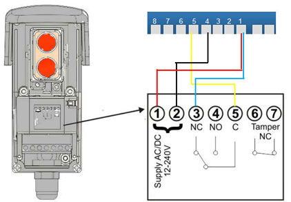
Use the RED colour wire and connect from the positive terminal 1 on the Road 400 to positive terminal on the both photo cells.
Use the BLACK colour wire connect from the minus terminal 4 on the Road 400 to the minus terminal on both photo cells.
Use the Blue colour wire from terminal 1 (which is also called the common terminal) to the RX photo cell unit Normal Closed (NC).
Use the Yellow colour wire from terminal 5 to the RX photo cell to COM terminal.
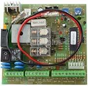
8 7 6 5 4 3 2 1


RX


_
+
+
_
+
+
NC
COM
NO
COM
NO
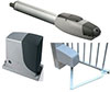
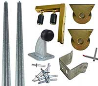
Related Products
Wiring a Third Party Safety Photo Cell beams to a NICE Road400 Sliding Gate


Positive
Minus
NC (normally closed)
Common
Minus
NC (normally closed)
Common
Photo Cells
RX
TX
1
1
1
4
4
1
1
4
5
5
Numbers on the NICE 400 Control Board
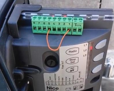
You will need to remove the bridge wire between 1 and 5 when installing photo cells


Only need to supply wire from the motor to the photo cell
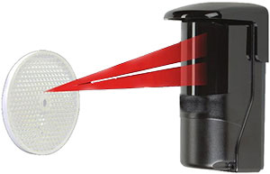
Across the driveway no wire the beam sends and recieves from one unit
8 7 6 5 4 3 2 1
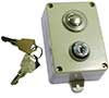

Push Button wiring no polarity
I am a bit confused with some reflectors PE beams some work with NC while others work only with NO connected.
TX
Connecting a push button or intercom
Power for external units use
8 7 6 5 4 3 2 1
24V (+)
0 (-)
Wiring Photo Beam to Nice Road400
Delivering
Australia-wide
and WorldWide
Australia-wide
and WorldWide

2005 - 2022 - Gatesplus, Australia
* Price subject to change without notice
Tasmania - *3 Days Delivery
* delivery times may change see Terms & Conditions
* delivery times may change see Terms & Conditions
Perth - Fast and in Bulk - *3 Days New Service to Perth (Business to Business)
Orders on stock items received will be shipped the next Day - Mon - Fri
Sydney, Brisbane, Melbourne & Adelaide- *2 Days delivery

Delivering
Around Australia Daily
Around Australia Daily